
Make your P&ID a route into live asset information.
Create process and instrumentation diagrams, connect symbols to equipment, and open the records behind inspection status, documents and maintenance history.
Keep the asset and the evidence together.
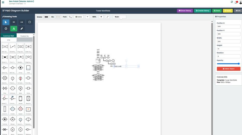
A drawing becomes more useful when its components connect to the equipment register. Heimdall's interactive P&ID builder lets users navigate from a system view to the relevant asset information instead of searching through disconnected lists and folders.
A practical working sequence.
Agree the scope, responsibilities and review points with your team. These stages show the process to establish around the equipment and records.
- STEP 01
Engineering · Define the system
Select the process or equipment system to represent and confirm the drawing scope.
- STEP 02
Engineering · Create the diagram
Build the customised P&ID using symbols and connections appropriate to the system.
- STEP 03
Asset team · Link the equipment
Connect symbols to the correct asset records and functional positions.
- STEP 04
Technical team · Review the links
Check that the diagram reflects the equipment and that each linked record is the intended one.
- STEP 05
Crew · Open the information
Select a component to access its asset details, documents, inspection information and work history.
- STEP 06
Engineering and asset owner · Maintain the view
Review the drawing and record links when equipment or system arrangements change.
What happens when the information is incomplete?
A missing asset record or uncertain symbol link should become a verification task. Confirm the equipment identity and drawing relationship before relying on the diagram as an operational information source.
The resulting record
- A customised interactive system diagram
- Symbols connected to asset records
- A visual route to documents and work history
- A review process for equipment and drawing changes
Understand the workflow.
Which systems can be represented?
The existing examples include choke manifolds, mud systems, hydraulic circuits, BOP control systems and other process systems. Discuss the drawing scope and information requirements with Heimdall.
Is the diagram a substitute for engineering approval?
No. Engineering teams retain responsibility for the suitability and approval of drawings. The platform connects the diagram with the equipment information used by the operation.
Walk through your own requirements.
Discuss the equipment, people and evidence involved in your operation. See how the workflow could be configured with Heimdall.
Request a Workflow Demonstration